

Aquila Kytori
-
Posts
1,222 -
Joined
-
Last visited
Content Type
Forums
Blogs
Knowledge Base
Posts posted by Aquila Kytori
-
-
On 8/5/2024 at 4:47 AM, Chic Aeon said:
And I haven't seen "when" DAE files will be no longer available in Blender just "sometime in the future". So if there is any definite answer it would be good to know.
Hi Chic
")
I did a little research and according to Monti29 ( Bastien Montagne )
"Starting from Blender 4.2LTS release, Collada file format support will be marked as legacy. This means that only minimal maintenance effort will be spent on it from now on, and that it will be removed in a later release (either 4.5 LTS, or 5.0)."
https://devtalk.blender.org/t/moving-collada-i-o-to-legacy-status/34621/39
The scheduled release dates for Blender 4.5 LTS and 5.0 are July 2025 and November 2025. https://developer.blender.org/docs/release_notes/compatibility/
So the answer would seem to be the second half of 2025.
-
 1
1
-
-
Selecting the object and using copy (Ctrl+C) then pasting(Ctrl+V) to create the copy will result in duplicated materials being created and assigned to the copy :

Instead of the above use Duplicate Object (Shft + D) to create the copy, this will result in the same materials being assigned to the new object :

-
 1
1
-
1
-
-
If all you want is the simple avatar .obj file from that wiki page:
- Just click on the relevant link.
- Select and copy all the text from the pastebin page.
- Paste it into a text editor (notepad will do)
- Save it to your desktop as a .txt file.
- Find the file and rename it, changing the file type from .txt to .obj
If you need a fully rigged Bento then you can download a .blend file from here : https://www.avalab.org/avatar-workbench/
-
1
-
Hi Niklas
This error has appeared several times in the mesh forum when uploading both non rigged
and rigged mesh.
So without more information I don't think you are going to get an answer to your problem.
Can you post some screenshots of your model in Blender and in the uploader. The more screenshots the better the chance someone will be able to spot/suggest something.
-
For the LOD3 Negative Scale error check out my post in this earlier thread :
-
1
-
-
Hi
Thats a new one to me. Can you share your file?
-
Another option is to upload as a single mesh object ...
For SL a single mesh object can have up to 8 material faces, If I understand correctly your porch is using 8 materials so no problem with joining all the smaller objects into a single object. Just make sure that after joining the porch has only one UV map in the list of UV maps. (Before joining the names of the UV maps of each of the smaller objects should have the same name, for example UVmap).

The Physics model should be as simple as possible, If you follow the 3 basic rules mentioned in the screenshot below then the physics model will work as expected. ( As Chinrey noted in her post above, the reason your physics model was not accepted is because you were not complying with Rule number 3, many small triangles in your physics model. Only create surfaces in your physics model where you actually need collision surfaces).


There are two types of physics model Planes/Triangle type and Box/ Hull type.
Planes type uses planes/triangles to create the collision surfaces. The larger you can make these planes the better. Its rule 3 again
. The larger the average plane size used in creating the physics model the lower will be the Physics Cost. This type of physics model should not be Analyzed in Step 2: of the Physics tab when uploading. It is this type of physics model I am using for this explanation.
The Box type physics model is where you create the collision surfaces using simple non overlapping box shapes. This type of physics model should be Analyzed in the Step: 2 of the Physics tab in the mesh uploader.

Finally, when rezzed it is necessary to change the Physics Shape Type from the default Convex Hull to Prim

-
2
-
1
-
-
......... and after trying the above :
If you haven't already, before exporting you should Apply the Location, Rotation and Scale before exporting.
In Blender > Object mode > select object > Ctrl + A (to open Apply menu) > choose the All Transforms option.
This will set the X Y and Z locations to 0m,
X Y and Z rotations to 0°
and X Y and Z scales to 1.00
-
1
-
-
Try exporting from Blender using the SL+opensim static preset, see screenshot below:

-
And should you like to sing along as you "shake your bacon" here are the lyrics in both German and English
-
1
-
-
As Quarrel has already said, avoid trying to texture across the ankle seams especially when using geometric patterns.
As a test I tried a different approach, Create custom UV's for the mesh then Bake the texture from this new UV map back to the original.
- Duplicate the mesh, and redoing the UV seams.
- Add a new UV map to the list
- With this new UV map selected re-unwrap the mesh.
In the Shader editor add the fishnet pattern image texture (diamond pattern) and for input use this new uv map.
Note in the following example I only did it for one of the avatars legs :

so far so good
Next is to bake the resulting texture from the new UV layout back to the original SL UV map.
5. In the shader editor add a new Image texture (named Bake in the screenshots below). This will be the where the texture will be baked to. Connect up a UV Map node and have it using the original SL UV map.
6. From the list of UV maps select the original SL UV map.
7. In the Render Properties panel set up the bake settings.

8. After baking connect up the output from the "Bake" image texture node to the input socket of the Principled BDSF shader to see the baked texture (using the SL UV map) on the mesh.

If we now zoom in on the area of the ankle seam we see the deformed texture exactly as Quarrel predicted. Squished Uv's result in warped texture and low pixel density.

If you check the SL Market Place you will find others having the exact same problems when trying to create fishnet stockings using the SL avatar template.
This is why most avoid the SL template problem by creating their own mesh fishnet stockings so that they have full control over how they are UV unwrapped.
For Tattoos :
I would suggest looking for tutorials about how to paint directly on the avatar body using stencils.
example :
And if, for example, you need to stencil the tattoo across the Upper body and Lower body then look into how to set up and paint across UDIM tiles in Blender.
I haven't tried this but in theory, joining the Upper and Lower body parts to be a single object then setting out the Lower body UV's onto a second UDIM tile, you should be able to paint/stencil a tattoo texture directly on the mesh which will result in the tattoo appearing on both tiles. When finished you should have separate upper and lower body textures with the tattoo spread across them.
To move the Lower body UV's across to a second UDIM tile, select the Lower body UV's then use the keyboard shortcuts G X 1 .This will move the UV's by exactly 1 tile along the X axis.
-
3
-
3 hours ago, IvyTechEngineer said:
OBTW, when I upload the model to SL the texture needs to be separately uploaded?
Yes ........ but instead of having to upload a separate image texture for each of the student's names it may be more interesting for you to create a texture consisting of all the students names on a single texture ? Then use the Vertical and Horizontal offsets in the SL build floater to select which name appears on each model.
In the example below I set out 20 "Student Names" in two vertical columns of 10 names on a 1000px² . 10 names per column makes it very easy to use the vertical offset up/down arrows to select a name from the list.
In Blender create a little single sided Label Object and UV unwrap and map it carefully to the first name in the list of names :

Next Duplicate this Label Object. This new duplicate Label object will be later joined to the students model:

Hide the original Label object.
Select the duplicate label object and the students model then use Ctrl + J to join them to be a single object.
Next, in edit mode reposition the name label approx. 1mm above the surface of the students model. If necessary resize the label as required.

Repeat the above for each of the students models.
No need to mess about with the UV's to select the correct name for the label in Blender, that will be done when rezzed inworld.
The model should now have 2 (at least) materials assigned to it. One for the model and one for the label.
When rezzed inworld edit the model and with the Select face enabled in the SL build floater select the Label face and apply the List of Student Names texture to this face.
Set the Alpha Mode to Alpha Masking and Mask Cutoff to something above zero.
Now all that is left to do is change the Vertical Offset using the up/down arrows to select the correct name for the label.
For names in the second column set the Horizontal Offset to 0.5 :


-
In Blender > with your Wings Top object selected > Object Data Properties tab > UV Maps, check to see if you have more than one uv map in the list of UV Maps.

For SL, an object can only have one UV map (with up to 8 material "layers"). If there are more than one uv map in this list then only the first (or selected) uv map will be exported and used on your model in SL.
If the wrong UV map is exported with the object you will find that the uv islands of that object will have been scaled down to a single point on the uv space resulting in what you are seeing, thats to say the material faces of the object will display the colour of a single pixel from the applied texture.
So instead of the expected UV mapping :

the UV map will have the above 2 UV islands scaled down to a single point and the result will be something like this :

The fix is to only have the one correct uv map in the list and delete any others
or when exporting to .dae, make sure that you have the correct UV map selected and in the Collada export options panel have the "Only Selected Map" checked.

Another earlier thread on this subject can be found here :
-
My guess is that your teacup, teabag etc are all one object in blender and that if you look in the Data properties tab > UV Maps you will find that you have more than 1 UV map in the list !
For SL a single mesh object can only have 1 UV map (with up to 8 materials assigned to it). If an object does have more than 1 UV map in the list of uv maps then only the selected UV map will be used. any part of the mesh using the other uv maps will be zeroed to a single point at the bottom left-hand corner of the UV space resulting in the effect you getting . see image and gif below.
IF this is the case you will need to
1: Separate the object in Blender by UV map (or material ) so that you have the same number of objects as UV maps.
2: Then rename the appropriate UV map for each object so that all the objects will be using a UV map with the same name.
3: Delete the unused UV maps from the list for each object.
4: Delete the unused materials from the list for each material.
5: When done join the objects back to be a single object again.
This should result in a single object with a single UV map. When, in edit mode with everything is selected the UV's will look a mess because all the UV islands will be overlapping but when selected by material all will be good
In the example below I have 1 object (3 meshes ) 3 UV maps. The Cube UV's uv map is selected in the list of UV Maps :


Separating into 3 objects and renaming the appropriate UV map to UV map for all 3 objects. All 3 objects uv map have to be given the exact same name so that when joined to a single object again only this 1 name will appear in the list of UV Maps :

The result 1 object and 1 UV map with 3 materials :

Selecting by material as one would in SL :

-
1
-
-
It seems a little odd to me that is necessary to have the Vertical scale value set to 2.9 which would have the effect displacing your texture vertically so that the transparent part of the texture will be mapped to the "text face" and then need to use the Vertical offset 0.4 to correct this by bringing the text (MARI) back into view, but I guess that was a deliberate choice by the creator.
Can you check the Vertical scale and Vertical offset values are set the same when you are wearing the necklace.

-
2 hours ago, Manes Siamendes said:
So exactly what size do the physics meshes have to be in relation to the actual meshes? Do they need to fit within the actual meshes, or do they just have to be the size of the actual meshes' bounding boxes?
Yes its the bounding box X Y Z dimensions of the physics model that should match (approximately at least) the bounding box dimensions of the visual model.
If the physics BB is not the same as the visual objects BB it will be stretched or squished to size by the SL mesh uploader.
If necessary you can view the BB of an object in Blender by selecting the object >Object data tab > Viewport Display > Bounds.

Is there a particular reason why you have separated the spiral stairs into 3 separate objects the way you have?
-
1
-
-
3 hours ago, Manes Siamendes said:
I optimized the physics mesh so it has less triangles and made the center pole a triangular prism as well.
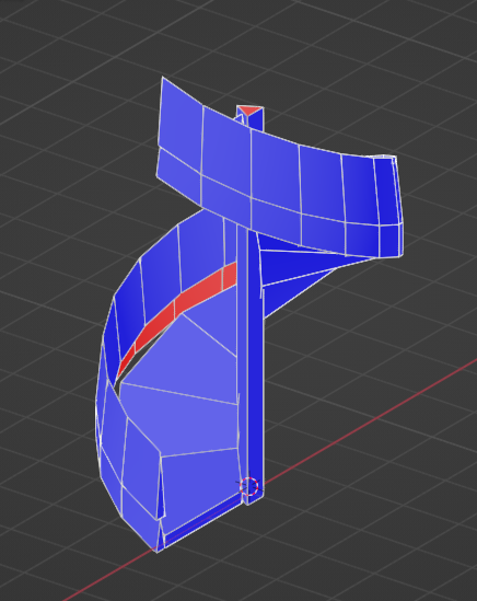
When walking up a narrow spiral staircase in SL it is very easy to "walk up over" the outer rail and fall off. To avoid this increase the height of the rail as much as possible in the Physics mesh.
Something like in the gif below, blue is the physics model for the rail object:

Also increasing the height of the physics rails will increase the size of the triangles in the physics model which has the benefit of lowering the physics cost !
Link to a thread dealing with a spiral staircase :
-
1
-
-
3 hours ago, Manes Siamendes said:
also renamed all three physics meshes in Blender to the following:
spiralStairs_PHYS
spiralStairsRail_PHYS
spiralStairsCenter_PHYS
I bundled all three of them in one Collada file, 'spiralstairs_PHYS.dae." The main model is in 'spiralstairs.dae.' But when I tried putting it all in the uploader, I still am getting the same problem. The stairs mesh is still grabbing the center physics mesh and the center pole is still grabbing the stairs physics mesh.
If you also have the 3 high lod models named exactly the same (without suffix) then it sounds like you are doing everything correctly.
Quick test using my own spiral staircase but using your object names:
High Lod objects:


Repeat for Physics objects:
.thumb.png.1df0f9f51fe9fa0b3aeb6ecf6e3bf59f.png)

When Uploading to SL, select the spiralstairs.dae file (containing the 3 high lod objects) then you should find that the spiralstairs_PHYS.dae file has been automatically loaded into the Physics tab for you :

Note that in Blender I tried selecting the objects in different orders before exporting and it made no difference. Each time the physics models were aligned correctly to the visual models.
If you are still having problems post a screenshot of the full Blender window and maybe we will spot something. or better still share your Blender file
3 hours ago, Manes Siamendes said:Just what else am I doing wrong? I want to upload the whole thing consisting of three linked meshes each with its own corresponding physics mesh combined into one object. Is that simply not possible?
A link to an earlier post about uploading linksets of LOD and Physics models
-
1
-
-
Hi
If the texture looks OK in Blender but different when applied to the object in-world then usually it is because the object has more then 1 UV map linked to it in Blender.
Check to see if this is the case, Properties panel > Object Data tab > UV Maps. If more then 1 UV map either delete the one that you are not using or before exporting, select the correct UV map then in the Collada export panel use the SL+Open Sim Static presets which should automatically checks the Only Selected UV Map option.

 5 hours ago, Namuri said:
I would also like to point out that on SL I can only use Convex Hull or None. I can't choose Prim because there's not (I use last version of Firestorm)
If you don't see the Prim option it is because in the SL mesh exporter > Physics panel you did not specify a Physics model to use.
You can create your own custom physics model in Blender and choose to use that in the Physics panel > Step1: Pick a physics model (From file option) or simple choose the Cube option from this drop-down menu. This Cube will be stretched X Y and Z to fit your visual models bounding box.
The in Step2: Convert to Hulls hit the Analyze button.
.thumb.png.f8ebf9e0e8c74cb6287f4523a553bf3b.png)
-
1
-
-
40 minutes ago, Butler Offcourse said:
When I finish the shoes, would this rotation cause me issues?
That was my question as well
Hopefully someone with more experience will be able to asnwer that.
My thinking was it would be easier to model the shoe with the foot straight and sole flat to the floor. Then if necessary, you could copy and paste it back in to the original file and rotate the shoe a little to fit the foot etc.
-
4 hours ago, Butler Offcourse said:
But I have a slight problem:
- I did select the armature from the outliner as you have adviced me to do so.
- Then I went to the running green man, and I clicked on the rest position
But as you can see on the screenshot, nothing has changed for me. Am I doing something wrong or am I not doing something completely?
My knowledge of rigging and weight painting is minimal so what I am suggesting below could be completely wrong but I think it will be OK for your shoe creation.
To me it sounds like the Pose Position (A pose) has been applied as the Rest Position (T pose) ? Both Pose and Rest Positions are the same.
To get back to Rest Pose = T pose and Pose Position = A pose .................... your going to love this lol : thanks to Jaroslav Jerryno Novotny at https://blender.stackexchange.com/questions/49768/can-i-set-my-pose-position-like-the-new-rest-position
Starting from where it seems you are with at Rest and Pose Position the same :

First save your file with a new name because ....... just because
Returning to the "default" Rest Position :

Looking at your original screenshot and comparing foot position to background grid , to me it looks like the mHipLeft and mHipRight bones have been rotated 5 degrees that's why in the next step we are going to rotate them back by 5°. (and 5° is not just some random number so makes sense).
With X axis mirror enabled any rotation we do on the left side will automatically be mirrored on the right side :

Remove Armature modifier from body and feet:
.thumb.png.ded801b239b7f5817d2ab6a9ff8682b9.png)
Applying this pose as Rest Position :

Adding back the Armature modifier to body and feet objects:

This next step is optional, it is recreating the Pose Position (A Pose) the same as before :

Rotating mHipleft (along with mHipRight) minus 5 degrees :

Now we have a Rest Position and a separate Pose Position :

-
1
-
-
Hi again
17 hours ago, Butler Offcourse said:So I opened the dev kit, but I am confused. The toes are not alligned from the position that the avi is standing. Like the pinky toes are higher than the big toe. How should I do the shoes? I should just do parallell to the toes and it will be fixed in sl once the avi is using the AO..etc? I added a slight curve to make it look less shocking and more straight, but I have no idea if it is the correct technique? Because by doing it the way I am thinking of doing, the sole doesn't sit flat on the floor as you can see on the screenshots
It looks like your model is in an A pose, (legs slightly spread) which results in the soles of the feet not being flat on the floor. In Pose mode the mHipLeft and mHipRight bones have been rotated a little so that there is more space between the thighs which helps when creating and weighting some items of clothes. (for example pants/trousers).
When creating your shoes it would be better to have the model in the T pose, the default position of the armature, (no bones rotated in pose mode, the legs are straight, ankles closer together and the thighs usually touching). The soles of the feet will be flat to the ground.
If the above is the case then It maybe as simple as switching from the Pose Position to the Rest position in the Properties panel.
In Object mode > Select the Armature from the Outliner > Object Data Properties (little green running man icon) > and from the Pose options switch from the Pose Position to the Rest Position. see images below :


Note:
If needed it is possible to clear the bone rotations made in Pose mode (resetting all bones rotations to the default T pose again)
Object mode > Select Armature > Pose mode > A key to select all bones > Alt R to clear all rotations.
Now back in Object mode the Pose Position will be the same as the Rest Position.
-
1
-
-
2 hours ago, vanettda Lassard said:
I have deleted the offending faces to show what I'm working with and these three edges show up but only in object mode.
If edges are showing in object mode but not in edit mode perhaps in edit mode, you have accidentally hidden (H key) a part of the mesh ?
In edit mode does Alt + H to unhide change anything?
Best is, if you can share that part of your model so that we can have a better look
-
I'm not expecting you to do this but just letting you know that if necessary you can walk around your build in Blender.
In Object mode > View > Navigation > Walk Navigation (Right mouse click this option and Add to Quick Favourites).
Adding to Quick favourites makes it easier to switch to this walk about navigation mode.

Now when ever you want to go walk about, in Object mode hit the Q key to open your Quick favourites menu and choose this Walk Navigation mode.
In this mode cross hairs will replace the mouse cursor. Position the cross hairs at the place you want to start your walk and hit the space bar. Use the arrow keys and mouse to move around the build.
Left or Right click to return to the normal navigation again.

Some Walk options can be set in Preferences.
.thumb.png.c2ec66676af4f1d7e68e1eef1147dfbb.png)
Oh and make sure the ground plane is very big because if for whatever reason you fall off its a very very long way down..........


.png.9956736ac961389899ab5f317ea8275a.png)


.png.877bdbe41653a6f65fe4c69c9ede2139.png)


.png.dd70ae4ab6f9cd89fbe7cc3066c47235.png)


.png.b576b85023574cc224cecc822c75ae65.png)
 Facebook
 Instagram
 Twitter
 YouTube
 Flickr
Dae Parsing
in Mesh
Posted · Edited by Aquila Kytori
Hi")
Take a look at this earlier thread:
The OP's very first image shows where you can find the the Log tab in the SL uploader.
If in your log it also states that the issue is LOD3 Negative scale detected ............................ then scroll down to my post on what that means and how to fix it in Blender before exporting. (Ctrl A > Apply > Scale)
If you have a different error log message then copy and paste it here so that somebody may be able to tell you what it means.
Here is another thread with a parsing error (that also had the LOD3 Negative scale detected log)
but this time when checking the mesh, the problem was found to be that the larger loops at the top and bottom of the chain were still bezier curves. Converting these to mesh before exporting from Blender fixed the issue.